Solar PV Design Guide
A practical guide to the drawings, checks, calculations and project information behind a strong solar PV design. Use it to understand what affects system size, array layout, yield, grid connection, mounting, electrical design and project documentation before a project moves too far.
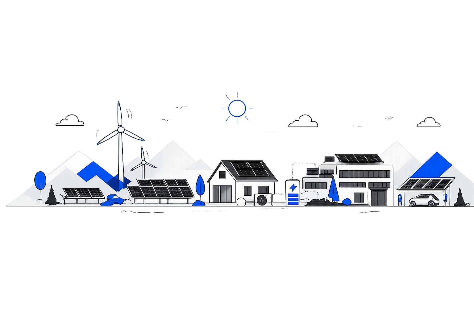
PV DESIGN BASICS
A strong solar PV design connects roof space, electrical capacity, energy demand, compliance requirements and real site conditions into a single coherent plan.
What good solar PV design brings together

-
What a solar PV design actually needs to decide
A solar PV design is not only a drawing with panels placed on a roof or site. It is a sequence of technical decisions that must work together.
A useful design should answer these practical questions:
· Where can modules safely and sensibly be installed?
· How many modules make sense for the available area, energy demand and connection capacity?
· What will shading do to annual generation and daily output?
· How should modules be grouped electrically into strings?
· Which inverter arrangement is suitable for the site and the project objective?
· How will the modules be fixed, supported or ballasted?
· How will the system connect to the existing electrical infrastructure?
· What drawings and documents are needed for installation, approval, procurement and handover?
When these questions are answered clearly, the project becomes easier to price, approve, build and maintain.
-
Good design starts with good input data
The quality of the design depends heavily on the quality of the information provided at the start. Missing drawings, unclear electrical information or unconfirmed site constraints often lead to redesigns, delays or unrealistic expectations.
Site and roof information
Useful information includes roof plans, elevations, site plans, drone images, roof covering type, roof pitch, parapet heights, skylights, plant areas, access zones, fragile roof areas and any known structural limitations.
Electrical information
A design should be based on the real electrical supply. Useful information includes the point of connection, main incoming supply, distribution board details, existing generation, metering arrangement, earthing information, available capacity and any known export limits.
Energy use information
Annual consumption is useful, but half hourly data is far more valuable where available. It shows when electricity is used, how much can be consumed on site and whether the system should be optimised for self consumption, export, battery storage or future loads.
Project objective
The best design depends on the goal. A project designed for maximum roof coverage may look different from 1 designed for self consumption, export revenue, PPA modelling, carbon reduction, battery readiness, planning constraints or staged future expansion.
-
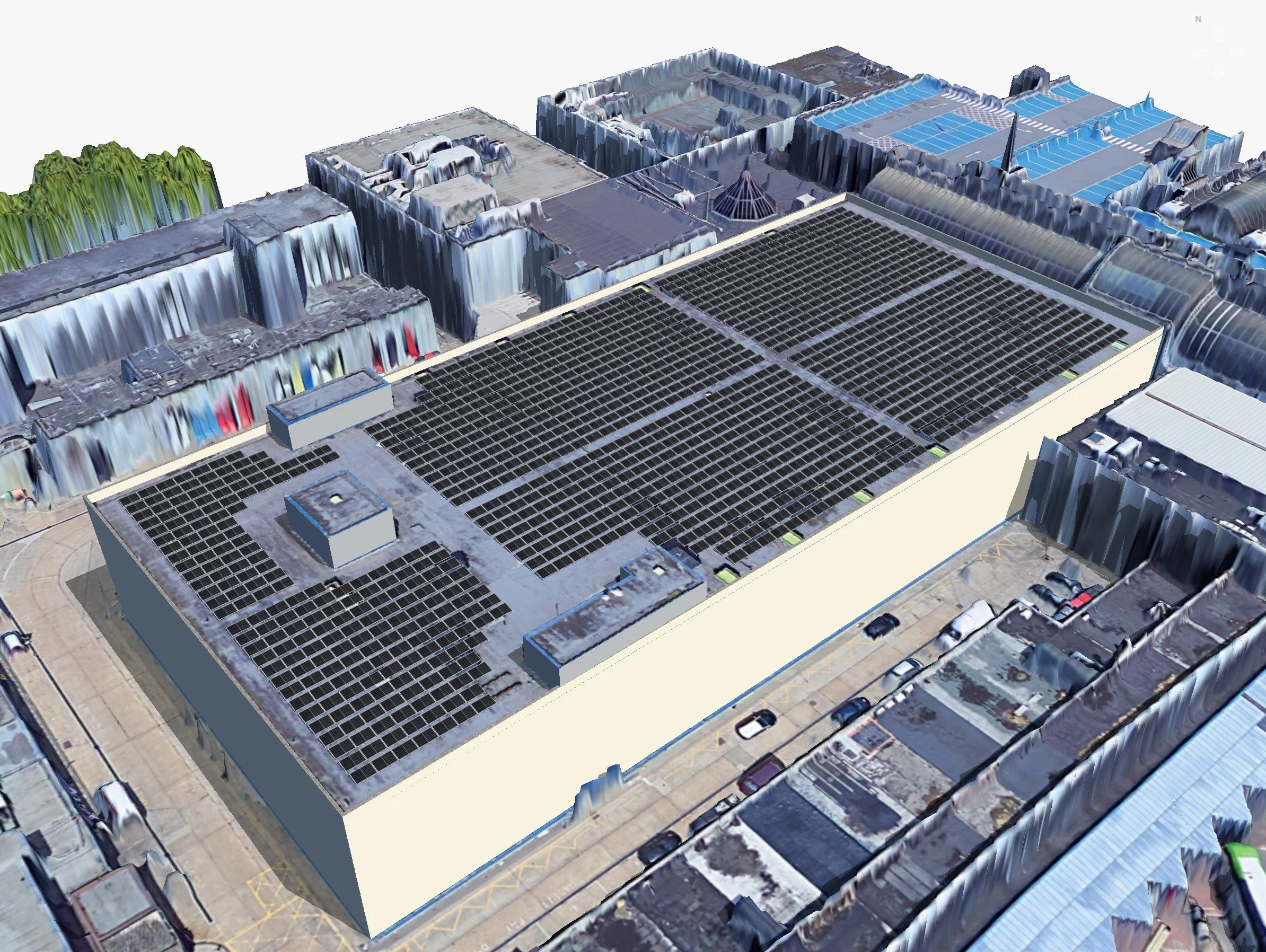
Usable area is not the same as empty area
A common mistake is to treat every empty roof space as available solar area. In reality, a solar layout must account for access, maintenance, roof zones, fire access, drainage paths, obstructions, wind exposure, warranties and safe installation practice.
What should be checked
· Roof geometry, pitch, orientation and available module zones.
· Obstructions such as vents, rooflights, plant, parapets, chimneys and existing equipment.
· Shading from buildings, trees, roof features and future developments where known.
· Access routes for installation, maintenance and emergency considerations.
· Roof covering type, fixing method, ballast potential and waterproofing constraints.
· Structural limits, wind exposure and any requirement for separate structural review.
A good layout does not force modules into every available corner. It balances capacity, yield, safety, maintenance and buildability.
-
The right system size depends on demand, capacity and purpose
The largest possible system is not always the best system. A strong design considers how much electricity the site uses, when it uses it, how much export is allowed, what the roof or land can support and what the client wants the project to achieve.
Main sizing factors
· Available roof or land area after practical exclusions.
· Annual electricity consumption and half hourly demand profile.
· Import capacity, export capacity and electrical infrastructure limitations.
· Expected self consumption and export behaviour.
· Future loads such as EV charging, heat pumps, process electrification or building expansion.
· Budget, payback target, PPA assumptions and carbon reduction goals.
A commercial or industrial site with strong daytime demand may justify a larger PV system than a site with low daytime load, even when both buildings have similar roof space. This is why consumption behaviour matters as much as roof area.
-
Yield estimates are only useful when assumptions are clear
Solar yield is affected by more than the number of modules installed. Orientation, tilt, shading, module type, inverter selection, cable losses, temperature, soiling, downtime and modelling assumptions all influence the final estimate.
What a yield review should explain
· Annual generation estimate in kWh.
· Specific yield where relevant, usually shown as kWh per kWp.
· Assumptions for orientation, tilt, losses and system performance.
· Shading impact from surrounding buildings, trees and roof features.
· Monthly generation profile, not only annual generation.
· Any limitations in the model caused by incomplete information.
A realistic yield estimate is more useful than an optimistic estimate. It helps clients, investors and project teams make decisions with fewer surprises later.
-
String layout, inverter selection and protection need to work as 1 system
The electrical design connects the module layout to the real electrical infrastructure of the site. It must consider voltage, current, inverter limits, cable routes, protection, isolation, earthing and the point of connection.
String layout
The string layout shows how modules are grouped and connected to inverter inputs. It must respect voltage limits, current limits, temperature effects, module orientation and inverter MPPT configuration.
Inverter selection
Inverter selection affects efficiency, monitoring, clipping behaviour, export control, stringing options, roof zone flexibility and maintenance. The inverter arrangement should suit the system size, site layout and electrical connection strategy.
Protection and cable design
Cable sizing, voltage drop, isolation points, protective devices, AC connection, DC routing and earthing all need to be considered. These details are critical for safe installation and clear handover.
The single line diagram should show how the system connects electrically, what protection is included and how the main components relate to each other.
-
A solar layout is only useful if it can be built safely
Mounting design affects module spacing, load distribution, roof warranties, drainage, fixing points, ballast, wind resistance and maintenance access. It should be considered early, not added after the panel layout is already fixed.
Roof mounted systems
For flat roofs, the design may need ballast zones, wind calculations, parapet effects, row spacing and maintenance walkways. For pitched roofs, it may need rail positions, fixing points, roof covering details and safe cable routes.
Ground mounted systems
For ground mount projects, the design should consider row spacing, tilt, terrain, access tracks, fencing, cable routes, inverter locations, soil conditions and the chosen mounting structure.
The mounting approach can change the final module count. A technically strong design treats structure, electrical layout and site access as connected decisions.
-
Design around the point of connection from the beginning
Grid connection requirements can influence system size, inverter selection, export control, protection settings and project timescales. This should be considered early, especially on commercial, industrial and larger residential projects.
What needs attention
· Existing supply capacity and connection arrangement.
· Proposed inverter capacity and export expectation.
· DNO application requirements where applicable.
· Export limitation strategy where required.
· Protection settings, metering and monitoring requirements.
· Clear single line diagrams and supporting technical documents.
A design that ignores the grid connection can look attractive on paper but become difficult to approve or operate. The connection strategy should be part of the design from the start.
DESIGN DOCUMENTS
These are the drawings, reports and schedules that turn a solar PV concept into a usable design pack. Not every project needs every document, but each one has a clear purpose.
PV design documents explained
-
A scaled plan showing the proposed module positions, orientation, spacing, roof zones, obstacles and design constraints.
-
An assessment of how shadows may affect generation across the year, often supported by 3D modelling and site specific geometry.
-
A generation estimate showing expected output, losses, assumptions and monthly or annual performance.
-
A drawing or schedule showing how modules are electrically grouped and connected to inverter inputs.
-
A simplified electrical diagram showing the main components, connection points, protective devices and relationship between the PV system and the site supply.
-
A more detailed electrical representation where required, showing components, connections and circuit relationships.
-
A drawing showing how modules are supported, fixed or ballasted on the roof or ground structure.
-
A drawing showing the proposed cable paths from arrays to inverters and from inverters to the electrical connection point.
-
A plan showing where inverters should be installed, with consideration for access, safety, heat, environment and cable routes.
-
A list of the main equipment and quantities needed for procurement, pricing or installation planning.
-
A marked up drawing showing changes made during installation or review, often used to record real site adjustments.
-
Final drawings updated to reflect the installed system rather than the original proposal.
-
A checklist used to verify the system before handover, including safety checks, settings, tests and documentation.
DESIGN DOCUMENTS
Most PV design problems are avoidable. They usually appear when site conditions, electrical limits, shading, mounting or operational details are not checked early enough.
Common issues that weaken PV designs
Site operation ignored

Opening hours, process loads, maintenance zones, future equipment and sensitive roof areas can all change the best design approach.
Mounting reviewed too late
Mounting affects spacing, weight, roof suitability, warranties and final module count. It should be considered early.
Poor source drawings
Outdated plans or missing elevations can cause wrong module counts, missed obstructions and avoidable redesign.
Unconfirmed electrical capacity
Designing before the connection point and available capacity are known can lead to inverter, export or DNO changes.
Weak shading assumptions
Trees, parapets, nearby buildings and roof plant can reduce output if they are not modelled properly.
Overfilled layouts
A high kWp layout can create access, shading, mounting and maintenance problems if practical constraints are ignored.
DESIGN SUPPORT
When to ask for design support

Use specialist support when site information is unclear, the roof or land area is complex, the electrical route is uncertain or the project needs reliable outputs for pricing, approval or installation.
Nortcel can support feasibility layouts, detailed PV design, yield modelling, single-line diagrams, mounting coordination, grid documentation, energy analysis and independent design review.

Need to turn a solar opportunity into a clear design direction?
Share the project information with Nortcel and we can help assess the site, define the right design approach and prepare the outputs needed to move the project forward with confidence.